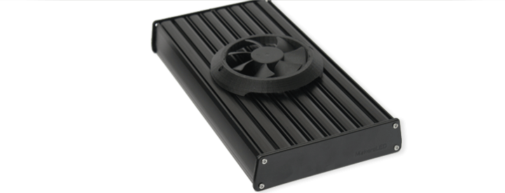
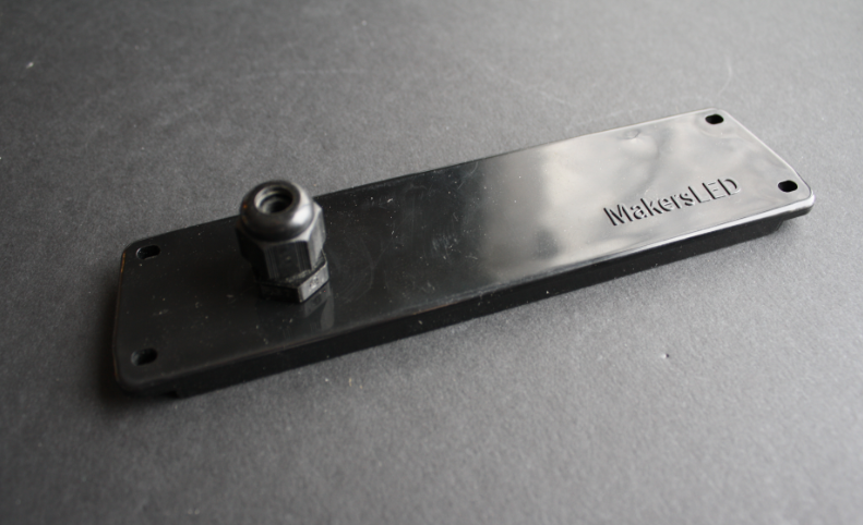
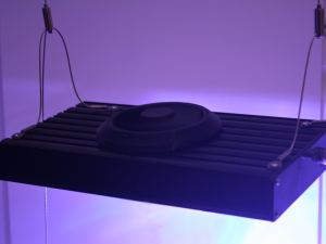
In this blog post we’ll build up a MakersHEATSINK Slim with the 70W Lumia 5.2 LED module.
Supplies:
- SLIM Heatsink Kit: Includes endcaps + plexiglass + hardware (MakersLED MakersHEATSINK SLIM)
- 70W LED Module, 5 Channel (LEDGroupBuy Lumia 5.2, using Cree LEDs)
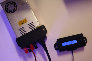
- 5 Channel LED Driver with Meanwell LDD Driver Modules (MakersLED MakersDRIVER 5up PRO)
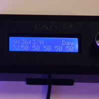
- LED Day/Night controller (MakersLED MakersCONTROLLER)
- 48V DC Power Supply, with MakersLED Power Supply Cover
- Power Connector (optional)
- 2 Conductor (2 Pin) Power Connector
- 90MM frameless fan, 3D Printed Fan Cover
Even though LEDs are considerably more efficient than other light sources, they still create heat and require a heatsink to ensure a long lifetime…
Step 1. Screws, Washers, and Nuts come with the kit (25 LEDs/foot).
Install the insulating nylon retaining washers onto the screws:
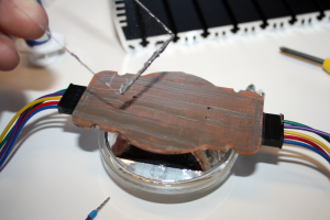
Step 2: Apply a *thin* layer of thermal paste to the 70W LED.
*Remember, thermal paste is a poor thermal conductor when compared to aluminum or copper — BUT, much better conductivity than the tiny air gaps that would otherwise exist between the surface imperfections on the LED module and the heatsink.
Step 3: Install the screws and nuts into the appropriate heatsink t-Slot.
The t-Slots allow the flexibility to change the LED fixture at any point.
Step 4: Slide 4 screws+nuts up to the 70W LED module and tighten them snugly to create a solid thermal connection to the heatsink.
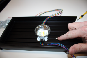
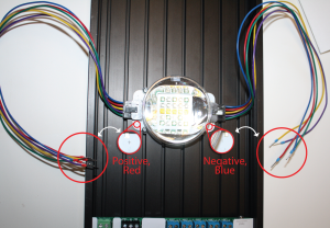
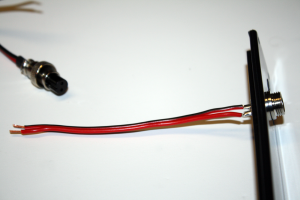
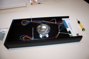
Step 5: Install Wires on Lumia 5.2 LED Module w/ Cable Harness. Note the (+) and (-) terminals on the Lumia 5.2 LED Module. Install the cables such that the blue wire ends are negative and the red wire ends are positive.
Slide the MakersDRIVER into the Fixture.
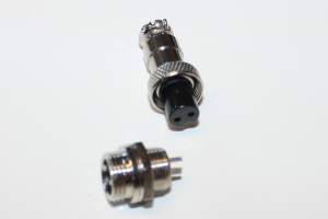
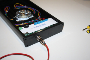
Step 6: Prepare the 2 pin (2 conductor) 1/2″ endcap connector
OPTIONAL: A cord connector/cable gland would also work if you prefer not to solder)
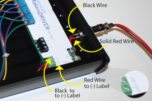
This connector is where the 48V power will enter into the LED fixture and power the MakersDRIVER LED Driver.
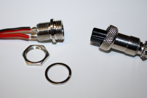
Solder a short 18 gauge wire onto the panel mount side of the connector, then an 8ft wire segment to the outer connector to connect to the power supply.
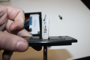
Each pin on this connector is labeled: “1” and “2” – on both the panel mount side and the wire mount side. Be sure to follow these labels (ie, use Red Positive= 1 and Black Negative =2) when soldering both connectors. If you do not, and cross pins, you will have a short!
(see this chart for chassis wire sizing)
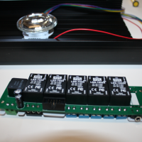
Step 7: Install the MeanWell LDD modules onto the MakersDRIVER
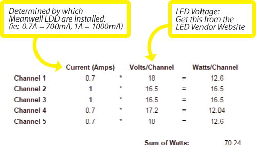
Install the Meanwell LDD modules onto the MakersDRIVER 5UP PRO. These little black cubes determine the amperage your LEDs are driven at for each channel.
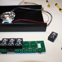
For this case 700mA, 700mA, 700mA, 1000mA, and 1000mA LDD’s were used.
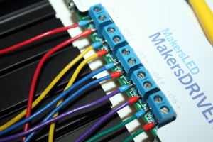
Step 8: Wire the Lumia 5.2 LED to the MakersDRIVER 5UP PRO
Each wire color set on the 70W LED represents its own channel (there are 5 channels on this LED module).
Again, note the (+) and (-) on both the wires and labels next to the blue terminal blocks. Attach Red wire ends to (+) and Blue wire ends to (-) using a flat blade screwdriver:
Step 9: Land the 48V DC power wires onto the MakersDRIVER 5UP PRO green terminal block as shown in the photo.
The wire can be routed underneath the MakersDRIVER.
Warning: If you accidentally install these wires backwards at any point, with power applied, you will need a new fuse. Watch close!
Step 10: Zip tie the extra wire slack to tidy things up:
Step 11: Wire up up your 48VDC power source (no power applied)
Here we used the MakersLED Power Supply Cover with a 48V power supply for quick tool-less binding post connections.
Idea for improvement: the 1/2″ 2-pin panel connector used in the endcap could be swapped out with a binding post for a foolproof connection to the power supply.

Step 12: Plug in the MakersCONTROLLER into the jack on the MakersDRIVER (it looks like a headphone jack).
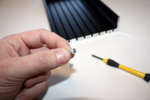
Finishing: Install the plexiglass/acrylic splash shield and endcap screws.
Don’t apply power yet!
Step 13: Double check everything! Do not apply power in this step.
A good test step is to use a multimeter to test continuity on your wiring. Continuity is the presence of a complete path for current flow.
Switch to the ![]() icon on your multimeter and touch the leads together – it will beep if there is a connection between the probes.
icon on your multimeter and touch the leads together – it will beep if there is a connection between the probes.
- Touch a multimeter probe the positive side of the 48V power supply and the positive side of the green terminal on the MakersDRIVER – it should beep to show a good electrical connection for the 48V power path.
- Next, try the reverse -touch the negative rail on the power supply to the positive side of the green terminal. It should not beep!
Next, double check that you have the LED lead plus’es and minus’es lined up on the MakersDRIVER (this is less sensitive to getting backwards, but lets make sure it is correct so it works the first time!).
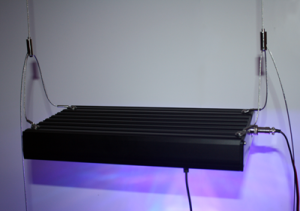
Do not continue until you have correct connections and you are confident you have the correct continuity! If everything checked out, go ahead and plug in the 48V power supply and watch it light up. Do not look directly into the LED!
Step 14: Thermal Testing
Next, we’ll run it for an 1.5hours and check the thermal performance – with and without a fan.
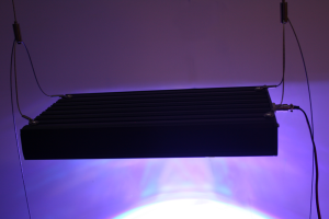
At 100%, fixture is running a full 70W of power. How do we know? Wattage = Volts * Amps:
Without a fan this slim heatsink is tested to cool about 33Watts of LEDs/1ft heatsink. With a fan it’s cooling capacity goes up considerably, up to 100Watts/1ft heatsink.
 No-Fan Configuration:
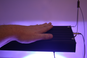
With the fixture running at 35W (all channels at 50% intensity on the controller), the max heatsink temperature was 65C. This is a safe temperature for Cree LEDs, but at 65C, you cannot comfortably hold your hand on the heatsink. Remember, this is with no fan — natural convection and radiative cooling only.
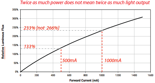
If you do run this no-fan configuration, you will want to swap out the 700mA and 1000mA LDD’s for 300mA and 500mA LDD’s, respectively. With the lower amperage drivers, when you run 100% on all 5 channels, you will not exceed 33W. At the lower amperage you do lose some light output, but your LEDs will be more efficient, output less heat, and will last longer. The violet chips on the Lumia 5.2 will appreciate the lower currents also (violet/UV LEDs are generally not as robust as the whites and blues).
Sidenote: The LEDs are always driven at the amperage set by the LDD Drivers.When the controller set to 50% intensity, it is telling the MakersDRIVER to turn off and on the LEDs at a rate of 1000 times per second: 50% on and 50% off. Since this is happening so quickly it appears to be always on, due to your eye’s persistence of vision.
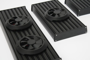
 With Fan Configuration:
With a low speed fan you can run considerably more LED wattage. Next, we installed a fan and turned all channels up to 100% (70W) and let it run for 1.5 hours. The maximum heatsink temperature was now 29C (85F). Only warm to the touch!
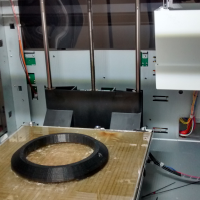
Step 15: Optional, 3D Printing a Fan Cover
MakersLED offers all their plastic part models online, so you can download the STL files and print them yourself.
Go to Thingiverse.com and download the fan cover for the MakersSLIM heatink fan cover and print if off.
The cover works with a frameless 90mm fan and attaches with #4-40 screws and nuts by using a T-slot built into the top of the heatsink (same T-slot the hanging kit uses). A small hole can be drilled into the T-slot to run the fan power wire into the LED housing to be powered by the MakersDRIVER (or any ~12v source).